There are two mounting points for a gas spring, the ‘fixed’ and ‘moving’ mounting points.
As the names suggest, the fixed mounting point remains fixed, whereas the moving mounting point rotates through an arc as the application opens and closes.
As a rule of thumb when positioning a gas spring, Camloc start with the moving mounting point approximately 1/3 the length of the lid from the hinge as shown in figure two below:
_-_figure_two_b9786ebf.jpg)
Figure Two: Typical Gas Spring Positioning
This provides an extremely rough guide as to where to place a gas spring, but if this is developed further it will also give an indication of the size of the spring required.
Simple Moment Balance
If we begin by considering the application to be a simple moment balance without a gas spring involved, in basic mechanics terms the application can be considered as a second-class lever.
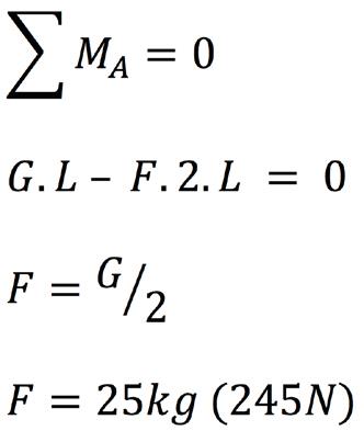
The application is pivoted at point A, the lid weighs 50kg (G) and the centre of mass is equi-distant at a length of L between pivot A and somebody holding the lid up at point B.
_-_figure_three_14fc16c2.jpg)
Figure Three: Simple Moment Balance A
To calculate the upward force (F), an individual must apply to keep the lid horizontal and in balance, using the formula below:
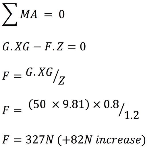
Taking this a step further, if the centre of mass is moved further to the right (away from the pivot), no longer being equi-distant along the hatch; the centre of gravity (XG) is now 0.8m from point A, with the total length of the hatch (Z) being 1.2m.
What is the upward force (F2) to point B required to keep the hatch open?
_-_figure_four_7122611e.jpg)
Figure Four: Simple Moment Balance B
This can be determined with the following equation:
Both solutions are simple because all forces are perpendicular to the beam and there is no gas spring involved. By including a gas spring, the problem becomes more complex.
Simplified Gas Spring Application
For the remainder of this section, we will refer to the following diagram and list of terms:
_-_figure_five_4fa69c3a.jpg)
Figure Five: Simplified Gas Spring Application
Z = Length of the Lid (m)
XG = Centre of Gravity (m)
LS = Radius of Gas Spring Force (m)
F1 = Opening Force (N)
G = Mass of the Lid (N)
F2 = Closing Force (N)
n = Number of Gas Springs
Including a gas spring to the earlier example, the size of the gas spring required can be estimated using the following (simplified) formulas. These use the principle of the line of action of a force.
To calculate the forces involved, two terms in particular should be taken into consideration:
LS – Radius of the gas spring force (m), this is the distance between point A and the centre line of the gas spring.
n – Number of gas springs per application (normally two).
The formulas are used to give an estimate of the minimum required force for a specified mounting geometry.
They will not provide optimum mounting positions and a better solution may be found using specialist software.
Opening Force Calculation
The force required to hold the lid open (F1) can be calculated using the formula:
Gas Spring Force (F1) = Mass of lid x Centre of Gravity / Radius of Force x Number of Springs
_-_figure_six_5684c23b.jpg)
Figure Six: Gas Spring Force (F1)