It’s one of the basic rules of manufacturing: As part complexity increases, so do machining and assembly costs. But what if there were a different way to produce metal parts, one with fewer limitations than traditional milling, turning, and grinding processes, and able to build complex parts in less time and with little human intervention?
Enter the industrial 3D printing process of direct metal laser sintering (DMLS). Through additive manufacturing technology, DMLS produces fully functional metal prototypes and end-use parts, simplifies assembly by reducing component counts, and offers virtually unlimited part complexity with no additional cost.
Gaining Support
DMLS works by slicing part models into paper thin layers and then “drawing” them with a laser in a bed of powdered aluminium, Inconel, titanium, stainless steel, cobalt chrome, and other metals. Starting from the bottom layer and working up, each metal particle is melted and fused to its neighbours, one layer at a time until the part is complete. The result is a fully dense metal product with mechanical strength and fatigue characteristics little different than—and in some cases exceeding—one machined from comparable wrought, forged, or cast material, but produced with minimal tooling costs, significantly reduced setup times, and little waste.
If you’re ready to climb aboard the DMLS express, there are a few things you should know first. Although the technology produces fully dense parts from high strength, corrosion resistant metals, certain part features are prone to warping and curl if not supported properly during the build process. The design of build supports isn’t something you as a product designer or engineer necessarily need to be concerned with, but you do need to know that some shapes are exceptionally difficult to build, and by altering your part design somewhat, costs may come down while product quality goes up.
Learning the ABCs
Let’s take the entire alphabet for example. One of the great things about DMLS is you can print a number of different components in the same build, provided they fit within the machine’s build chamber, which in Protolabs’ case, is a volume measuring roughly (250mm by 250mm by 250mm).
Let’s start with the letter A. Unless the horizontal crossbar is less than 2mm. across, vertical supports will be required beneath it to prevent warpage. Not a problem, but it’s going to cost a bit to grind or machine those supports away after the build. Same with a T—without supports beneath the overhanging top section, it’s going to curl up like a goalpost. Letters B, D, P, and R are especially problematic because the supports will be left inside the part, where they’re most difficult to remove. Curved shapes like O and Q fare no differently, unless the letters are quite small, about the diameter of a soda straw. In fact, about the only letters that won’t need any form of support are X and Y, provided the arms are angled at least 45 degrees from the horizontal.
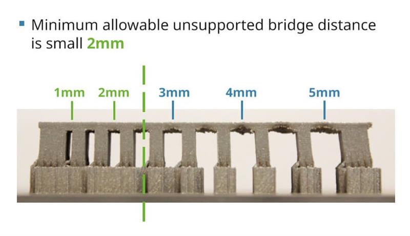
In the "alphabet" example in this design tip, the letter A represents a part with a horizontal crossbar. Unless that crossbar is less than 2mm across, vertical supports will be required beneath it to prevent warping, as this example shows.
Finding the right way
Wait a minute—why not just lay the letters on their backs? “Eureka,” you say, and go home early. In this case, all of the letter’s walls are vertical, and the only support needed is a series of interconnected vertical braces between the bottom of each letter and the DMLS build plate, sort of like the scaffolding used to support workers during a building renovation. These are easy to remove once the build is complete, and avoids direct contact with large, flat part surfaces that can warp or damage the build plate. This approach also provides the best surface finish, since roughness increases as walls deviate from vertical in DMLS-printed parts, and is worst on angled down-facing surfaces.
Wall thickness is another consideration. Thin walls below 1mm must maintain a wall height-to-thickness ratio of less than 40:1 or the structure may tumble. On the other end of the spectrum, very thick walls are wasteful and take a long time to build—better to hollow them out with a honeycomb or lattice structure, reducing material costs and processing time while preserving structural integrity.
Indeed, lattice structures are one of the best tricks up an additive magician’s sleeve. They’re virtually impossible to produce via conventional machining methods, but are fairly simple with DMLS. So too are treelike structures, gentle twisting seashell curves, and other organic shapes, all of which are cost-effective to produce with 3D printing—all that’s required is a little imagination and the right CAD software.
One final consideration is this: While Protolabs encourages product designers and engineers to think outside the box, it’s important to keep an eye on the finish line. DMLS provides the opportunity to push the limits on prototype and low-volume part design, but it’s not yet viable for high-volume production because of economic factors. It’s therefore an excellent idea to explain the entire product life cycle to someone knowledgeable in all types of manufacturing, so you don’t inadvertently design your product only to find it’s not scalable beyond a few hundred pieces.