1.0 Introduction to a Gas Spring
1.01 What is a Gas Spring?
Principally, a gas spring is the same as a mechanical coil spring; a device for storing energy. Although, a gas spring stores energy by compressing the gas contained inside, rather than straining material which makes up a coil spring.
1.02 How Does a Gas Spring Operate?
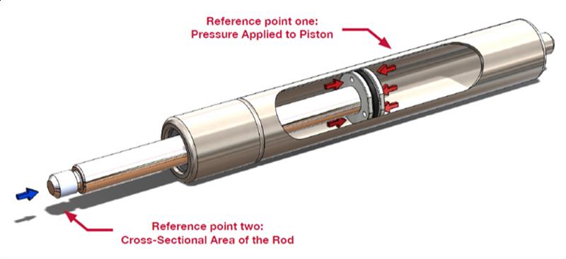
A gas spring is a closed system which requires no further gas to be introduced to the system for it to operate once charged with inert Nitrogen gas and manufactured. The pressure on either side of the piston (reference point one) remains equal no matter where it is positioned; this is due to the small cross-sectional area of the rod (reference point two) where the gas is unable to exert any pressure.
As the rod is pushed into the tube, the gas contained in the spring is compressed increasing the pressure, with the compression of the gas creating the spring-like behaviour. The piston attached to the rod allows the flow of gas across the piston and provides the means of controlling the flow of gas as the rod is depressed and extended.
2.0 Gas Spring Terminology
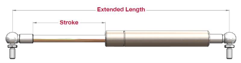
Stroke - The maximum amount of distance the rod can travel from closed length to extended length.
Extended length – The total length of the gas spring measured from the centre of one end fit to the centre of the next end fit.
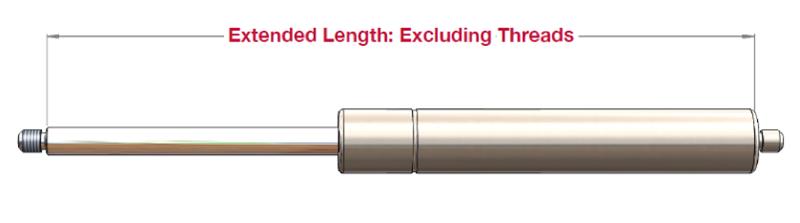
Closed Length – The total closed length measured from the centre of one end fit to centre of the next end fit.

There may be times when no end fits have been specified, this measurement will refer to the length from rod end to tube end (excluding threads).
Beadroll – The beadroll is the grooved section of the tube (reference point three). This feature is used to retain the guide and seal package and prevent the piston from damaging the seal package during extension.
3.0 Construction of a Gas Spring
A gas spring contains several components, each of which is integral for the safe and successful operation of the component.
3.01 Rod
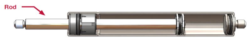
A rod comes as either precision ground, polished carbon or stainless steel and the surface is treated to improve wear and increase corrosion resistance. Generally, the rod will always be longer than the stroke of the spring (see Section 2: Terminology) and shorter than the length of the tube.
Carbon Steel can be treated in several ways such as chrome-plating, salt-bath nitriding and using a Nitrotec surface layer treatment. For Camloc’s carbon steel rods, we use a layer of Nitrotec surfacing as this has a number of advantages over the former methods. These include:
- Better wear resistance
- Lower frictional characteristics
- Corrosion resistance equivalent to stainless steel
- The process is environmentally friendly, non-toxic and produces no acidic by-products
3.02 Tube
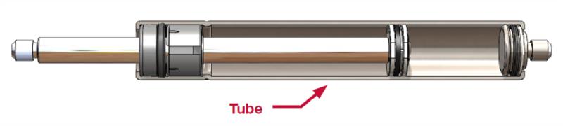
A gas spring tube comprises a high-integrity, powder coated, carbon or stainless steel seamless welded tube; which is suitable for high pressures.
The internal surface finish and tensile strength of the tube are critical for a gas springs longevity and burst pressure performance.
3.03 Guide and Seal Package
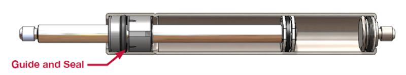
Manufactured from plastic composite, the guide and seal package provide a bearing surface for the rod and prevents the escape of gas and ingress of contamination.
As well as plastic composite, the guides used in Camloc’s gas springs can also be manufactured from zinc, brass or other materials with a suitable bearing sleeve incorporated. Rubber is used as standard for seals.
3.04 Piston Assembly
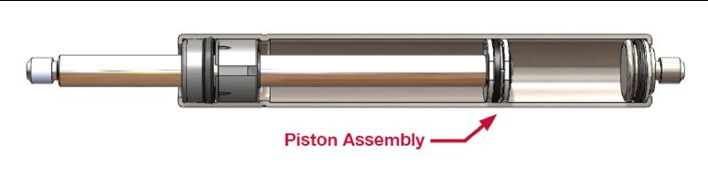
The piston assembly is manufactured from zinc, aluminium or plastic. For factors involving safety and preventing the rod being expelled from the spring, the integrity of the piston to rod attachment is critical.
The piston assembly controls the rate at which the gas spring extends and compresses.
3.05 End Plug
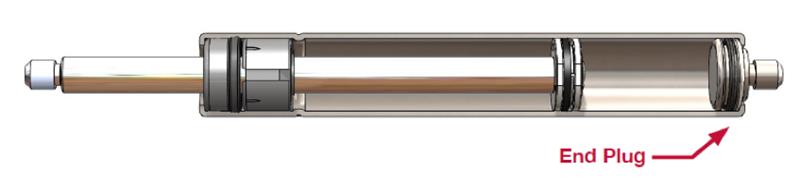
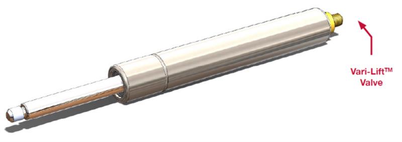
The end plug is used to seal the tube end of the gas spring, with this also attaching to the tube end fitting. Camloc’s Vari-Lift can be incorporated here where required, allowing for the release of Nitrogen gas and subsequent reduction in force of the spring.
3.06 Nitrogen Gas Charge
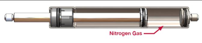
Nitrogen is used inside gas springs as it is inert and non-flammable, therefore not reacting with any of the internal components.
4.0 De-gassing a Vari-Lift
When gas springs are used, hinge friction, perceived speed of action, weight of application and where the gas spring is positioned on the application will have a bearing on calculations; leading to forces predicted prior to testing (theoretical forces) being incorrect.
Camloc’s Vari-Lift has been designed to save the end-user time and effort, offering the capability of being de-gassed whilst in position.
The gas springs are charged to their maximum force during manufacture. Using the standard 2mm Allen key provided, gas can be gradually released via the Vari-Lift valve. To do this; insert the Allen key into the Vari- Lift valve found at the end of the tube and make a quarter-turn. Once gas can be heard, make a quarter-turn back to close the valve prior to checking whether the application is running smoothly. If not, repeat the process.
Release of gas must be done on a gradual basis, to ensure too much is not released from the gas spring.