This tip will help you improve your part design, shorten run time, and maybe even save some costs along the way. The list comes from common issues our applications engineers have seen often in quote requests. It’s not an exhaustive list (only your closest relatives can tell you everything you’re doing wrong), but it hits some highlights.
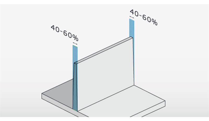 Strive for uniform wall thickness with moulded parts. If you do need to design thinner walls in certain places, they should be no less than 40-60% the width of adjacent walls.
1. Avoid Non-Uniform Wall Thickness for Moulded Parts
When designing a part for injection moulding, having the wall thickness come as close to uniform as possible will make for a stronger part. Otherwise, for example, thinner areas will tend to sink and warp. If you need to design thinner walls in places, they should be no less than 40-60% the width of adjacent walls. And watch out—some materials have quite specific thickness requirements to keep parts strong. Knowing material specifications can save you a lot of pain later.
2. Transition Gradually From Thick to Thin Areas in Moulding
No one likes weak, saggy parts, so here’s something to think about that will help you avoid them. After ejection from a mould, parts have to cool. Thin areas will inevitably cool faster than thick ones. That temperature differential can create weak areas, which lead to sink and warp. The solution is to avoid sharp differences in wall thickness, something we just touched on. Instead, create gradual transitions between these areas. You and your parts will be happy you did.
3. Be Cautious with C-Shaped Moulded Parts
No matter how you turn it, C-shaped parts are inherently weak, unless supported. Poorly designed moulded parts have a tendency to warp, especially when using glass-filled materials. Fibre-reinforced materials are used for their added strength properties, also for heat resistance. Fibres in the plastic counteract shrinkage effects due to molecular orientation whether in amorphous or semi-crystalline materials. But fibers don’t expand or contract as temperature changes, so fibre-filled materials typically experience reduced shrinkage in the direction of their orientation.
Because the fibres cause non-uniform shrink within the moulded part, supported C-shaped parts can warp even more than an unfilled material.
Build radii wisely, only in necessary areas, for example, to eliminate sharp edges on the surface of the part that an end user may touch, or in critical functional areas such as a lead-in to an assembly.
4. Consider Carefully Your CAD File Format
Sometimes we get CAD files that were translated from .STL files. While .STL files are acceptable for 3D printing, they create problems with moulded parts. That’s because they reveal the part’s surface as a series of triangles, rather than the true curves you would find on real parts.
The bottom line is that we will be unable to quote these designs and send them back requesting changes, which costs you time.
Instead, output your designs as STEP files using CAD software such as SOLIDWORKS, Inventor, Pro-E, Catia, or any number of others and define thicknesses clearly, then you’ll be good to go.
5. Use Radii Wisely for Injection Moulding
Building radii into a part can be a hit and miss proposition. Only use them in necessary areas, for example, to eliminate sharp edges that an end user may touch, or in critical functional areas such as a lead-in to an assembly.
Some radii are used on inside corners of critical features to make more robust geometry. Inside radii can also help on material flow patterns. In general, proper placement of corner radii can create stronger moulded parts.
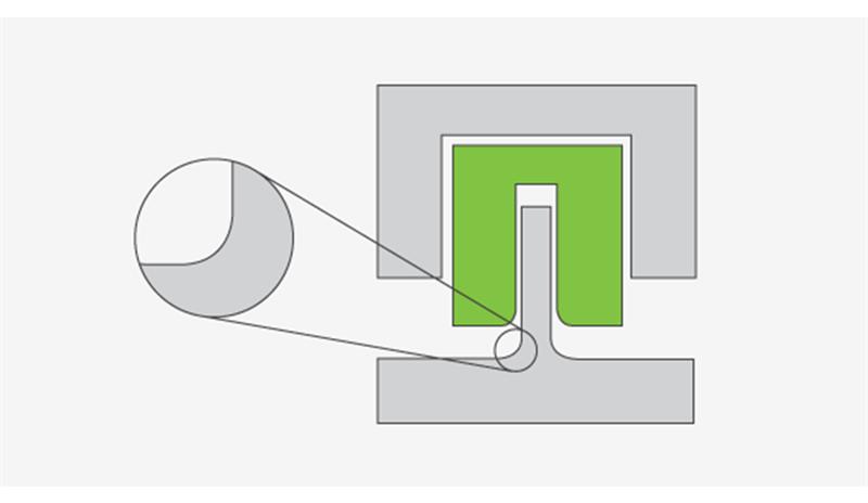
6. Be Careful with Parting Lines and Radii for Moulding
Parting lines always make for interesting design and manufacturing challenges. Typically, we want them to be as unnoticeable as possible, and deciding where to locate them is an exercise filled with aesthetic and mechanical considerations. But watch out. If you try putting a fillet or radius around a parting line, you might end up with undesirable minor undercuts in your mould and maybe even flash.
7. Eliminate Undercuts in Moulded Parts if Possible
Undercuts are features that make it difficult to eject a part from its mould. Sometimes these are created using techniques such as side-action cams or pick-out inserts, but these add manufacturing time due to moulding costs and complexity. If it’s possible to eliminate undercuts, it will definitely speed up manufacturing time.
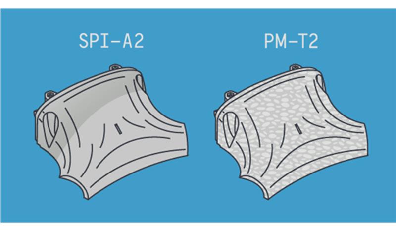
Cosmetic finishes aren’t always necessary, though Protolabs offers an array of available surface finishes if needed, including SPI-A2, which is a Grade #2 Diamond Buff, and PM-T2, which provides a medium bead blast textured finish.
Cosmetic finishes aren’t always necessary, though Protolabs offers an array of available surface finishes if needed, including SPI-A2, which is a Grade #2 Diamond Buff, and PM-T2, which provides a medium bead blast textured finish.
8. Determine if Cosmetic Finishes are Necessary
Cosmetic finishes are possibly the most overlooked piece of the design puzzle. If you don’t need them, don’t order them. You can always go back and add cosmetic finishes to future parts, if necessary. It’s yet another way to save yourself some time and expense. That said, if you do have any questions, don’t hesitate to call our applications engineers to discuss specific finish grades. Also, don’t forget that all-over finishes take longer to, ahem, finish, than targeting specific areas.
9. Treat Each Part as Separate Quote
Assemblies represent a collection of parts, and sometimes you only want one of those parts quoted and manufactured. Even if you want pricing on every element contained in an assembly, treat each part as a separate quote. It makes it easier for us to figure out what you want quoted, and doing that will help speed up the quoting process.
General Injection Moulding Rules that Totally Rule
Beyond those issues to avoid or carefully consider, here are some best practices items to keep in mind. We couldn’t go through all this information without listing a few things you should do.
Shutoff angles
Maintaining a 3-degree shutoff between mould components is critical for long-lasting, robust molds.
Text/Engraving
To get raised (embossed) text in your part, use engraving in your mould design. The text you mill into the mould will become raised text on your part. Milling the text into your mould is a fast process, leading to faster turnaround times. Also maintain at least 0.508mm stroke width to achieve clean text.
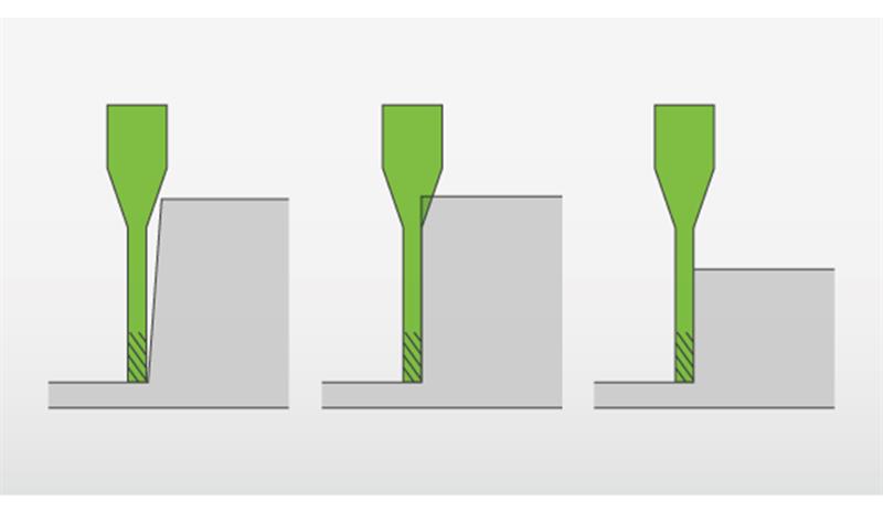
Adding draft angles to design helps facilitate ejection of a part from a mould and improves overall mouldability.
Adding draft angles to design helps facilitate ejection of a part from a mould and improves overall mouldability.
Draft/Thickness
Our standard injection moulding process relies on high-speed milling. As a general rule of thumb, use 1-degree of draft per inch of depth, and enough thickness to allow cutter penetration.
The Push and Pull of Injection Moulding
Remember to avoid unnecessary undercuts (see No. 7). Push/pull moulds—as compared to moulds with additional components or actions—not only save you money, but they also increase your expedite options.
Summing it Up
As always, no single design tip can cover all of the injection moulding mistakes we’ve seen, but this “best of” collection is a start. Take a look at our injection moulding design guidelines to keep you moving in the right direction.