Follow these brief design rules when designing for SLS or MJF processes using any of our powdered engineering grade materials: Adhere to minimum features sizes, minimise part warpage, minimise differential shrink, design for powder removal, and consult with us for part orientation.
1. Adhere to Minimum Feature Sizes for 3D-Printed Plastic Parts
We define the minimum feature size as the minimum survivable feature that will reflect what you see in your CAD model. Minimum feature size does not refer to how thin the layers are in the part. It refers to the size of a geometry that will both form and survive the finishing process. Listed below are three important issues we often see on parts that need to be addressed in the CAD model. Common geometries that can be problematic include blind holes, threads, and areas where internal diameters and tapers are in too close proximity to exterior walls.
Wall Thickness: This refers to the thickness in any direction on part walls or geometries. The minimum allowable wall thickness is 0.8mm - 1mm in SLS and 0.5mm in MJF.
Channel Gaps: This refers to the distance between two features. Channel gaps are important to consider when designing for 3D printed plastics because the sintering process can fuse two features together that do not account for channel gaps. We recommend minimum channel gap sizes of 1mm for both SLS and MJF.
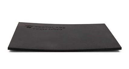
Be wary of part warpage with MJF and SLS, as seen in this warpage sample. Part size and overall thickness has the largest impact on part warping potential.
2. Minimise Part Warpage in SLS and MJF Parts
Powder-based printing processes like SLS and MJF use heat to sinter/fuse powder together into a solid part. The heat that builds the parts can also lead to undesired part warpage. Part size and overall thickness has the largest impact on part warping potential. The larger the part— 200mm and above being particularly difficult—the more likely the part is to warp. This is however also very dependent on the specific material under consideration. The thinner a part is and the closer it is overall to the minimum feature size, the more likely it is to warp. We recommend four options if you are concerned warpage may be an issue for your design.
1.Make the part close to the uniform thickness of 3mm to help ensure stability.
2.Opt for a glass-filled or mineral-filled nylon, like PA 12 40% glass-filled or Carbon filled Nylon (SLS materials).
3.If your part is above 200mm and you are concerned about warpage, another option is to run an unfilled PA 12 nylon material in our large frame SLS machine with build extents of 736.6mm by 635mm by 533.4mm.
4.A final option we offer is cut and glue.
3. Minimise Differential Shrink in SLS and MJF Nylon Parts
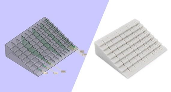
Similar to part warpage, differential shrink can occur when a part has non-uniform wall thickness. When one side of the part is exceptionally thick compared to the rest of the part, this causes the part to thermally cool at different rates. The thicker areas will cool much slower than the thin areas, and this can lead to undesired part shrink.
If a thick feature is required on the part, we recommend hollowing the feature to a feature thickness of 3-5mm.
4. Powder Removal with SLS and MJF
One excellent way to take advantage of 3D printing is to minimise material needed by including internal void spaces in your part. In the SLS and MJF processes, these areas will not have supports but they will have powder trapped inside of them. Trapped powder will require a drain hole designed into the model, which will be done for you, so excess powder can be removed after the printing process is completed.
5. Let Us Help with 3D-Printed Nylon Part Orientation
With regards to part orientation we recommend you let us orient your parts to further aid in minimising the risk of minimum feature resolution or part warpage.
Click here to read more design tips on creating plastic and metal parts for 3D printing, CNC machining, and injection moulding processes.