Whether you're an experienced engineer, student or enthusiast, you'll likely be wondering what an injection mould tool consists of. In this comprehensive guide, we will delve deep into the anatomy of a mould tool, unravelling its components, functions, and the process that occurs when it's in action.
What are the different block sizes for injection moulding?
The specific block sizes used in injection moulding vary based on a number of factors including mould design, machine specifications, material requirements, and the dimensions of the final product being manufactured. Here at Protolabs we can produce parts within the following dimensions.
Size: 480mm x 980mm
Volume: 966,837mm³
Depth: 101mm from parting line with 3° of draft, up to 280mm of the part
Projected Mould Area: 112,903mm2
What are the different elements of an injection mould tool?
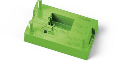
Mould A-Side
Cavity – the void or negative space within the mould that forms the desired shape of the product being manufactured. Essentially the inverse of the final product. When molten plastic is injected into the mould, it fills the cavity to take on the specific shape and dimensions of the finished product.
Clamp Pocket – a feature within the mould that assists in securely holding or clamping the mould halves together during the moulding process.
Leader Pin – Used to align and guide the two halves of the mould together during the closing process. These pins are typically cylindrical and are located on one half of the mould, fitting into the holes on the opposite half.
Locking Wedge Interface – a mechanism used to secure and tightly seal the two halves of the mould during the injection process. Prevents any mould misalignment or movement whilst the material is injected into the cavity.
Sliding Shutoff – a component within the mould that allows for the creation of undercuts or complex features in the moulded part. It’s used to create internal or external details that cannot bee formed with a simple two-part mould.
Sprue Hole – a channel or passage within the mould that allows molten material to be injected into the mould cavity. It’s the entry point into the cavity.
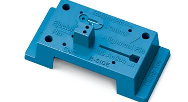
Mould B-Side
Clamp Toe – the area where the clamp force is applied to, in order to ensure the mould remains closed during the injection process.
Core – one of two main components used to create a desired shape. The core is the part of the mould that shapes the internal features of the final product. It is the interior surface of the part and creates voids, holes and other internal details.
Ejector Pin Holes – small cylindrical recesses or openings in a mould that accommodate ejector pins.
Leader Hole – hole used for aligning or guiding components during the assembly or disassembly of the mould.
Return Pin Hole – accommodates the return pin. The return pin is used in moulds with moving elements like slides or cores, to retract or return these elements to their initial / starting position at completion of the mould cycle.
Side-Action – also known as sliders, lifters, or side cores, are movable components within the mould that create features on the part that would otherwise be impossible or difficult to form using a two-part mould. These side-actions move perpendicularly or at an angle.
Side-Action Track – path or guide along which the side-action components move within the mould. The tracks are designed within the mould to facilitate the controlled and precise movement of the side-actions.
Part
Clip Feature – a specific part or featured designed into a moulded product that enables it to be attached, secured, or fastened to another component or surface.
Cold Slug – a portion of unmelted or partially melted plastic that enters the mould during the early stages of the injection process. Usually occurs when there’s inadequate or inefficient heating and melting of the plastic material in the injection unit.
Edge Gate – a gate that allows molten plastic into the mould cavity. It’s called an “edge” gate because it’s positioned at the edge of the part.
Sprue – the primary channel or passage through which molten plastic enters the mould cavity. It’s the initial pathway that connects the moulding machine’s nozzle to the runners in the mould.
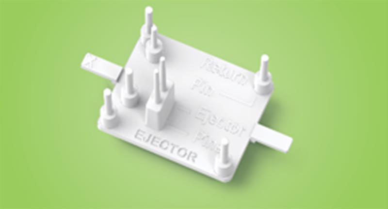
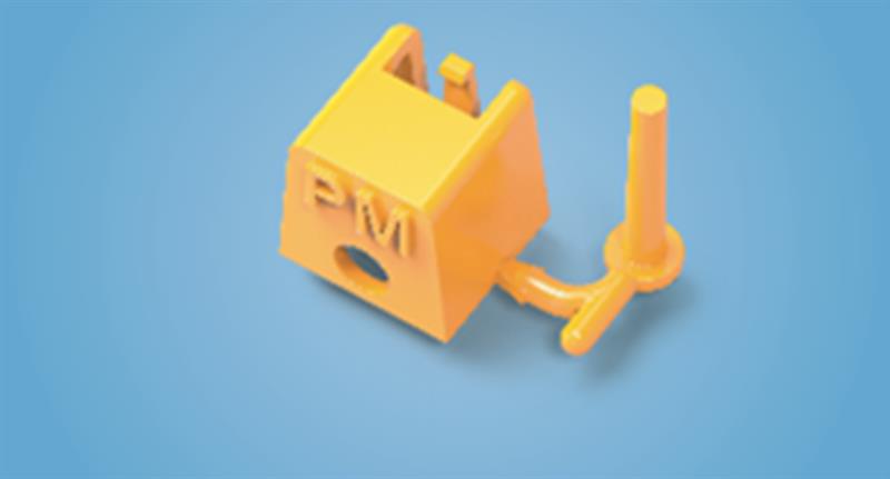
Ejector System
Ejector Pin – used to push or eject the finished part out of the mould cavity, once the moulding process is complete. Ejector pins are located in specifically designed holes or recesses in the mould and extend into the mould cavity and exert force on the part to push it out of the mould.
Ejector Plate – a flat plate or section within the mould that contains multiple ejector pin assemblies used to push the finished part out of the mould cavity.
Retaining Tab – a specific feature or component designed within a mould to secure or hold a movable part, preventing it from disengaging or moving unintentionally during them moulding process or while the mould is in use.
Return Pin – serves the purpose of retracting or returning movable components to their initial or starting positions after a moulding cycle is complete.
Guide – assists in directing the movement of a side-action mechanism within the mould.
Locking Wedge – a mechanism used to secure or lock the movement of a side-action mechanism within the mould.
What constitutes a well-designed part for injection moulding?
There are many factors to consider when designing a part. Before any design is sent for tooling, you need to perform the design for manufacturability (DFM) process. This is a systematic process that focuses on optimising a product's design to enable efficient and cost-effective manufacturing. The DFM process involves collaboration between design engineers and manufacturing engineers to identify potential challenges which might impacts the overall quality of the end-product and making refinements in order to overcome these challenges. The main steps in the process are:
- Design Analysis
- Design Optimisation
- Material Selection
- Prototyping and Testing
- Review
But what constitutes a well-designed injection moulded part? There are several critical factors to ensure successful and efficient manufacturing processes.
- Uniform Wall Thickness – consistent wall thickness throughout, promotes even colling, reduces warp, and minimises sink marks and voids.
- Rounded Corners and Fillets – reduce stress concentration points, minimise material stress and, improve mould filling.
- Ribs and Bosses – ribs provide structural support and bosses serve as mounting points or structural elements.
- Draft Angles – facilitates easy part ejection and minimises the risk of damage or sticking.
- Avoiding Undercuts – to reduce mould complexity, simplify ejection, and minimise production challenges.
- Gating and Venting – gates ensure even flow of material and even filling, whilst vents prevent trapped air or gases.
- Material Selection – crucial for meeting functional requirements, durability, and cost-effectiveness.
- Minimal Texturing – limiting textures surfaces or complex features reduces mould complexity and ejection challenges.
- Surface Finishes – aid in achieving desired aesthetic and functional qualities of a part.
- Consideration of Tolerances – designing within achievable tolerances ensures part consistency and facilitates cost-effective production.
A well-designed part not only considers the part’s functional requirements, but also aims to optimise the manufacturing process, reduce production challenges and ensure the final part meets quality standards efficiently and economically. For further information on how you can produce a well designed part with Protolabs, please view our Injection Moulding Toolkit, which not only explains our advisories and how to avoid them, but also gives further information on designing complex features for moulded parts.